ESR Project
by WD9GNX
Several years ago this author became familiar with the ESR meter while repairing audio
equipment at Fast Service in DeKalb. This device measures the Equivalent Series Resistance of
electrolytic capacitors. It can be used to check electrolytic capacitors in or out of a circuit but
not when the circuit is live or the capacitor is still fully charged. An ESR of less then 3 ohms
means the capacitor is good, 3 to 10 ohms is between good and bad or leaky. Above 10, the
capacitor needs to be replaced. As a point of information; electrolytic capacitors age in several
ways: They can become electrically leaky; causing a DC current through them that can make
them explode. They can shift in capacitance value. But the most common way they degrade, by
far, is by unduly increasing their Equivalent Series Resistance, which is the undesired internal
resistance that appears in series with the wanted capacitance at a given frequency.
We only had 1 ESR meter in the shop and it had a habit of being lost when it was most needed.
It occurred to me that such a device could be useful in my shack and it would be nice to keep one
in my tool box so it was available for use when I needed it. Unfortunately the cost of a
commercial unit runs $100 to $150. For as little use that it might see in my shack I decided to
build my own. After finding several articles on this subject I settled on the XQ2FOD version.
This unit required a transformer made with 400 turns of #30 wire and 20 turns of #26 wire with
an E shape ferrite core. Winding that transformer was a bit of a chore. In the following years I
built 2 more and sold them to Bob the owner of Fast Service.
In the April 2014 issue of QST, KG4BZW described a newer version of an ESR that didn’t
require a transformer. It looked simple enough so I decided to give it a go.
What follows is my method of attacking a project and the procedures used. This article is
intended to help others that wish to build projects.
After carefully reading the QST article and studying the block diagram and schematic I decided
to breadboard the circuit first. I have built other projects from the internet and wasted a lot of
time because they did not work as described or at all. So breadboarding first can actually save
time. Layout of the components on the breadboard is not very easy with the schematic that was
provided so my first task was to create a new schematic that showed the ICs with their pins and
the components connected to them. This makes it a lot easier to lay out the breadboard and
ultimately mounting the components on a proto-board. See QST_ESR_Schematic.pdf and
ESR_Schematic_052514.PDF.
During the breadboard test it was found that a 2.2 K ohm resistor produced 96.3 KHz signal.
The 2.4 K (original schematic) produced near 84 KHz. Also there was no 100 uA meter in my
junk box so I used a 50 uA meter which require a 10 K pot, not 5 K as specified.
Once I was convinced that the meter works as outlined in the QST article the next step was to lay
out the parts placement on the proto-board. A template was made and after hand drawing the
parts on the template a printable version was produced, see BoardLayout_02.PDF.
Link to BoardLayout_02.PDF
Link To QST_ESR_Schematic.pdf
Link To ESR_Schematic_052514.PDF
Page 1 of 3
L:\ElectronicsServicing\Electronics\ESR_Meter\ESR_QST_April2014\BuildESR_Article\ESRProject052614.doc
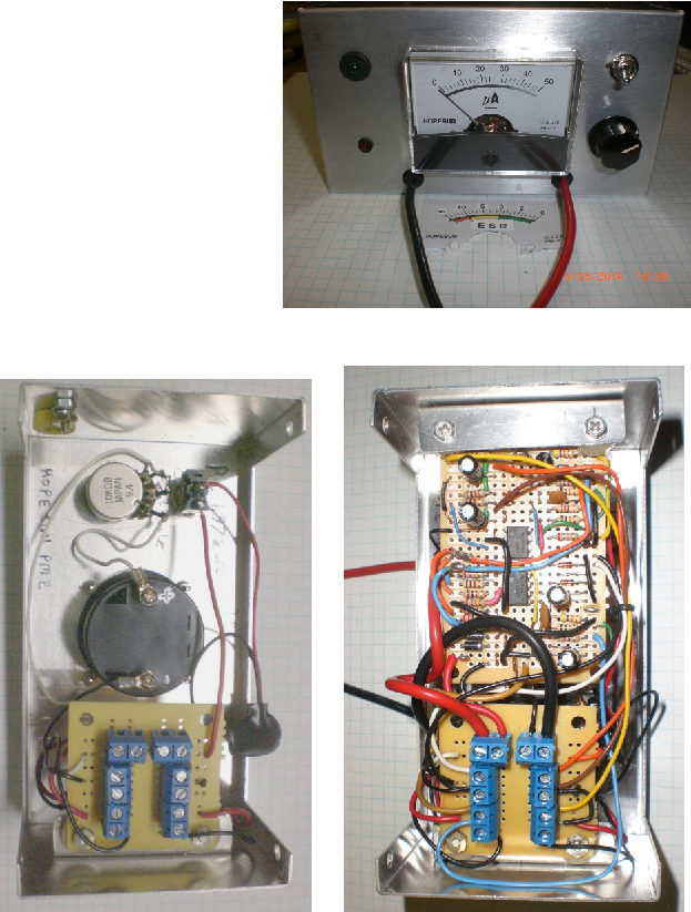
To make it easier to service the unit a
connection board was fabricated to
go inside the meter box and allow
connecting all the external wiring
from the proto-board to the various
parts inside the meter box. After
connecting all the proto-board leads
to the connection board a few more
tests were performed and when it
was found to be working as planned
the new meter face needed to be
made and pasted on the old meter
face. Final Testing and wa-la a
better designed ESR meter.
There were a lot of interruptions while building this project so it took over a month to complete
but it was, as always, a fun project.
2 LEDs under
Connection board
Page 2 of 3
L:\ElectronicsServicing\Electronics\ESR_Meter\ESR_QST_April2014\BuildESR_Article\ESRProject052614.doc
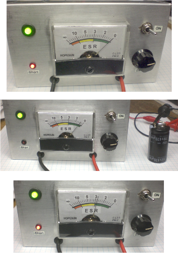
Final Tests
Zero Meter, note that Short LED is On
Good Capacitor
2.8 ohm resistor, DC short
Page 3 of 3
L:\ElectronicsServicing\Electronics\ESR_Meter\ESR_QST_April2014\BuildESR_Article\ESRProject052614.doc